If you’ve ever spent hours troubleshooting a CNC threading job—only to pull a part off the machine with stripped threads, chip welding, or a tool that wore out 20 pieces into a run—it’s almost certain you didn’t get the spindle speed right. As a CNC threading tools supplier who’s talked shop with machinists on shop floors across North America for 12 years, I can tell you this: spindle speed for threading isn’t a guess. It’s the make-or-break balance between material properties, tool geometry, and how your machine behaves. Most guys I meet either pull a number from an old bookmarked chart or crank the speed to “be efficient,” and nine times out of 10, that’s where things go wrong. Let’s break this down like we would over a cup of burnt shop coffee—no fancy jargon, just real stuff that works. Cnc Threading Tools
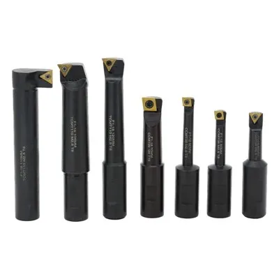
First, let’s get one thing straight: threading is different from turning or milling. When you turn a 1-inch diameter steel bar, you’re removing material in a steady, smooth cut that only touches the workpiece for a fraction of a second. Threading? You’re cutting a specific, repeated profile—usually 60 degrees for UNC or UNF, maybe 55 for BSPT—one edge of the thread at a time. Each pass lasts longer, the tool is engaged with the full depth of the thread, and the chip doesn’t just break away; it curls around the tool or the workpiece, building heat that can ruin both the tool and the part. That heat is directly tied to spindle speed, and if you get that wrong, you’re not just wasting tooling—you’re wasting hours of setup time, which is money you’ll never get back.
The biggest mistake I see new machinists make is using a generic spindle speed formula from a textbook. The old “surface speed (SFM) = (π × D × RPM)/12” line works for turning, but it’s incomplete for threading because you’re not cutting a full diameter every time. For external threading, the cutting diameter is the pitch diameter—not the major diameter you’d use for turning. Internal threading is even trickier, because the tool is recessed inside a hole, so chip evacuation is worse, and you’re limited by how much space there is for coolant to reach the cut. Let’s use a real example: if you’re threading a 1/2”-13 UNC bolt in 1018 steel, the generic SFM chart might tell you to run at 150 SFM. For turning the outer diameter, that’s great. For threading? Let’s calculate the pitch diameter first: 0.4056 inches. Plug that in, and RPM would be around 1,400. But I’ve run that exact job at 1,000 RPM, and it never had chip welding. Why? Because the formula doesn’t account for tool coating, thread pitch, or how the machine handles synchronized motion—something that’s non-negotiable for threading, by the way. If your CNC’s spindle and axis don’t sync perfectly, even the right RPM will give you a misaligned thread.
So how do you actually pick the right spindle speed? It starts with your material, because that’s the foundation. Let’s categorize the most common materials we supply tools for, and the speeds we’ve tested in our own demo shop over the last few years. For low-carbon steels like 1018 or 12L14, which are super machinable, you can push a little harder—between 80 and 120 SFM for high-speed steel (HSS) tools, and 150 to 200 SFM for coated carbide. Wait, coated carbide—another point no one talks about: tool material directly impacts speed. HSS is cheaper and works for low-volume jobs, but it softens at high temps, so you need to run slower. Carbide holds an edge, so you can run faster, but too fast and the insert will chip or crater. For stainless steels like 304 or 316, which work-harden as you cut, you need to go slower—60 to 90 SFM for carbide, because work hardening will grab your tool if you rush. I learned this the hard way a few years back when a customer called complaining that our threading inserts were failing after 5 pieces in 304. He was running 180 SFM, and each pass was work hardening the thread before the next cut even started. Dropping to 75 SFM doubled tool life, and he never called about that problem again.
Aluminum is another big one, and it’s got its own rules. You want to run as fast as possible here, because aluminum doesn’t build heat as easily as steel, and high speeds break up chips so they don’t weld to the tool. For 6061 aluminum, we recommend 250 to 350 SFM for coated carbide. The only exception is for fine threads, like 1/4”-20 UNF, where a chip can get stuck and break the tool. For fine threads, knock that speed down to 180 to 220 SFM. And don’t even get me started on titanium—Ti-6Al-4V, which is common for aerospace and medical parts. Titanium is gummy, it builds huge chips, and it’s super prone to galling. For threading titanium, you need to run slow—40 to 60 SFM for carbide, no exceptions. I had a aerospace machinist tell me he tried 100 SFM once, and the tool pulled 3 full threads right out of the part because the chip welded so hard. That’s not a speed mistake—it’s a material respect mistake.
Next, thread pitch. This is the variable that trips up even seasoned guys. Pitch is the distance between adjacent threads, measured in threads per inch (TPI) for imperial, or millimeters per thread for metric. Fine pitches (high TPI, like 20 TPI) mean each cut is shallower, so you can run a little faster. Coarse pitches (low TPI, like 8 TPI) mean each cut is deeper, so you have more material to remove, more heat generated, and more stress on the tool. For a 1/2”-13 UNC (13 TPI, coarse), that’s a 0.077-inch depth per thread, so you need to run slower than a 1/2”-20 UNF (0.050-inch depth per thread). I’ve seen machinists run a coarse thread at a fine thread speed, and the insert cracked before the first part was done. It’s like trying to dig a post hole with a spade vs. a teaspoon—one takes more force, so you can’t swing it as fast.
Then there’s machine capability and setup. You can have all the material and pitch data right, but if your CNC is old, has a loose spindle, or can’t hold tight synchronization between the spindle and Z-axis, you’re sunk. I always ask customers what kind of machine they’re running when they call for tooling advice. If it’s a Haas or Okuma from the last 10 years, with rigid tapping (wait, no—rigid tapping is for tapping, threading is continuous motion, but same sync), you can push speeds a little harder. If it’s an old manual conversion with a lagging encoder, you need to drop speed by 20-30% to avoid skipped pulses. Also, coolant matters. If you’re using a synthetic coolant that’s properly mixed, you can run faster because the coolant pulls heat away. If you’re using straight oil or just mist, you might need to slow down by 10-15% because the heat doesn’t dissipate as well.
Let’s talk about real-world tests, because numbers on a chart don’t mean squat if they don’t work on your machine. Last quarter, we had a customer threading 3/4”-10 UNF in 4140 pre-hardened steel (28 Rockwell C) for a hydraulic part. He was running at 120 SFM with our TiN-coated carbide inserts, and he was getting average tool life of 12 parts per insert. We asked to see his machine setup, and noticed he was only using 1 pass for the thread—coarse pitch, hard material, only one pass? That’s a problem. We recommended splitting the cut into 4 passes, and dropping speed to 90 SFM. His tool life jumped to 27 parts, and he had zero thread defects. He told me that was because the slower speed gave the chip time to curl and evacuate, instead of jamming in the thread. Another example: a medical parts shop threading M6-1.0 in 316L stainless. They were running at 80 SFM, and their internal threads kept having small burrs at the entrance. We bumped speed to 95 SFM, and added a 0.5-second dwell at the end of each pass. The burrs were gone, tool life went up, because the higher speed sheared the material cleanly instead of pulling it.
What about when you’re switching from external to internal threading? That’s a big one I don’t see discussed enough. Internal threading means the tool is inside a hole, so chip evacuation is way harder. Chips can get trapped between the tool and the wall of the hole, scraping the thread and breaking the tool. So for internal, you need to run 10-15% slower than the same external thread in the same material. I’ve seen a customer’s internal 1/2”-13 UNC threads fail because he used the same RPM for internal as external. The chip got stuck, pulled a thread, and ruined a $50 billet of aluminum. Dropping speed fixed it immediately.
Also, let’s debunk the “higher speed = better productivity” myth. Sure, if you run faster, each part takes less time, but if your tool wears out twice as fast, you’re spending more on tooling and more time changing inserts, which cuts into productivity. It’s a balance. We call it the “break-even point” in our shop. You test a range of speeds, from 10% below the recommended to 10% above, and track two things: tool life (how many parts per insert) and total cycle time. If running 10% higher cuts cycle time by 5% but cuts tool life by 40%, that’s not worth it. If it cuts cycle time by 5% and only cuts tool life by 10%, that’s a win. Every job is different, but this test takes 5-10 minutes, and it’ll save you way more time than guessing.
Wait, what about specialty threads? Like API threads for oil and gas, or buttress threads? Those have unique profiles that mean more material engagement, so you need to adjust speed even more. For API 8-round threads in 4140, we recommend 50-70 SFM for carbide inserts, because the thread profile is deeper and requires more cutting force. For buttress threads, which have a sharp edge that can chip, run 40-60 SFM, even in materials that would normally allow higher speeds. I worked with an oil and gas customer once who was chipping API thread inserts on every other part, and it turned out he was running 90 SFM on a 120 SFM job for standard threads. Dropping speed fixed the chipping, and he hit his quality targets.
Now, I know a lot of you are thinking, “This is great, but where do I get these numbers without guessing?” That’s where our team at CNC Threading Tools comes in. We don’t just sell inserts; we work with every customer to build a custom speed recommendation based on their specific job, machine, and setup. We test every insert in our demo shop across a dozen materials, pitches, and thread types, and we use that data to help you avoid the mistakes I mentioned earlier—generic formulas, ignoring material properties, skipping pitch adjustments.
If you’re struggling with inconsistent thread quality, short tool life, or frequent tool breaks, the first step is to start tracking your setup: what material you’re using, what tool you’re running, what pitch, how many passes, what coolant. Once you have that, we can walk through it with you, or you can send us a part drawing and we’ll give you a suggested RPM range and pass count. Don’t waste another cycle guessing at spindle speed—take the guesswork out of it, and you’ll save money, reduce waste, and get parts out the door on time.
To make this actionable, here’s a quick cheat sheet we keep on all our demo machines, for the most common jobs:
- 1018/12L14 steel (external, 10-15 TPI): 100-120 SFM (carbide), 80-90 SFM (HSS)
- 304/316 stainless (external, 10-15 TPI): 70-80 SFM (carbide), 50-60 SFM (HSS)
- 6061 aluminum (external, 15-20 TPI): 250-300 SFM (carbide)
- Ti-6Al-4V titanium (external, 8-10 TPI): 40-50 SFM (carbide)
- Internal threads: subtract 10-15% from the above numbers, and add an extra 0.25-0.5 second dwell at the end of each pass
But remember, this is just a starting point. Every machine, every setup, every batch of material is slightly different. The key is to test a small range around your starting number, track results, and adjust. I’ve had customers come back to us after following this process, saying they cut tooling costs by 30% and reduced rework by 50%. That’s not a magic trick—that’s just getting the spindle speed right.
At the end of the day, CNC threading is a precision operation, and the smallest adjustment can make the biggest difference. Spindle speed isn’t a trivial parameter—it’s the backbone of a good thread job. Skip the generic charts, account for material, pitch, tool type, and machine capability, and you’ll be pulling perfect threads every time, no troubleshooting required. If you need help dialing in the right speed for your next job, our team is here to help—we’ve got years of shop floor experience, not just textbook knowledge, so we’ll get you the solution that works for your specific operation.
Turning Inserts References
- DeVries, W.R. Analysis of Metal Cutting Operations. Oxford University Press, 2005.
- ASTM International. Standard Guide for Threading of Metal Materials for Machining Applications. ASTM B211-19, 2019.
- Okuma Corporation. CNC Threading Best Practices. Okuma Technical Publication, 2021.
- Machinist’s Workbench. Spindle Speed Calculations for Precision Threading. Custom Machining Journal, Vol. 47, No. 3, 2022.
Small Craftsman (Shandong) Machine & Tools Co., Ltd.
Small Craftsman (Shandong) Machine & Tools Co., Ltd. is one of the most experienced cnc threading tools manufacturers and suppliers in China, also supports customized service with low price. Please feel free to buy bulk high quality cnc threading tools in stock here from our factory. Contact us for pricelist.
Address: No.9 Quanxin Rd., Sishui Economic Developing Zone, Jining, Shandong, China.
E-mail: 6196@ocutchina.com
WebSite: https://www.ocutooling.com/
