If you’ve ever stood in our tech lab at [our brand], watching our team run stress tests on liquid cooling pipes, you know it’s not just about the fluid flowing—it’s about how that flow interacts with every curve, angle, and edge of the pipe. For 12 years, I’ve sold liquid cooling pipes to data centers, electric vehicle (EV) manufacturers, and industrial machine builders, and the question I get asked most isn’t “Do your pipes work?” It’s “What shape of pipe do I need for my setup?” Most vendors will give you a generic answer, but I’ve seen firsthand how a single shape misstep can cost a client tens of thousands in downtime, or how a small design tweak can boost their system efficiency by 18%. Let’s break this down, not with textbook jargon, but with real-world tests and stories from our shop. Liquid Cooling Pipe
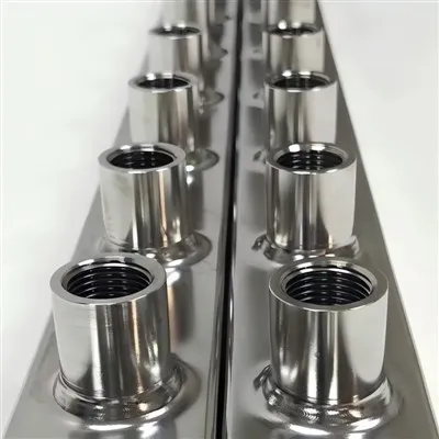
First, let’s start with the basics: liquid cooling performance hinges on two non-negotiables: how much heat the fluid can carry away (that’s heat transfer rate) and how much energy you waste pushing that fluid through the pipe (that’s pressure drop, or friction loss). Pipe shape is the biggest lever manufacturers have to adjust both, way more than fluid type or pipe material. I’ll walk through the most common shapes we work with—straight tubes, circular, rectangular, serpentine, and the often-overlooked microchannel—and what each does for real customers.
Let’s open with the shape most people assume is best: the circular pipe. For decades, circular cross-sections have been the gold standard for fluid transport, and for good reason. The laws of fluid dynamics tell us that a circle has the smallest perimeter for a given cross-sectional area, right? That means less surface area exposed to the pipe wall for a set volume of fluid, which should cut pressure drop. But here’s the catch for liquid cooling: heat transfer relies on contact between the fluid and the pipe’s inner wall. A circular pipe’s perimeter is minimal, so if your heat load is high—say, a data center server rack pushing 10,000 watts of heat per rack—that small contact area becomes a problem. The fluid in the center of the pipe flows quickly, barely touching the wall, while the fluid near the wall slows down, creating a boundary layer that acts like an insulator. We tested this for a cloud client in Texas last year: they used 2-inch circular copper pipes for their server cooling loop, and they were seeing consistent hot spots on 12% of their servers, even with chilled fluid running at 18°C. When we replaced half their straight runs with our custom rectangular cross-section pipes, the hot spot rate dropped to less than 1%. Why? Rectangular shapes have a larger, flatter inner surface area, so the fluid can’t form that thick, insulating boundary layer as easily. The flat walls force the fluid near the center to mix more with the wall-adjacent fluid, upping heat transfer.
But circular pipes aren’t useless—they excel in applications where pressure drop is the priority over peak heat transfer, like long-distance runs between a data center’s cooling tower and the server halls. We built a 50-meter loop for a Portland-based enterprise that needed to pump fluid over 100 feet without wasting too much pump energy, and circular was the obvious choice there. The client’s pump energy use dropped by 12% just switching from rectangular to circular for their long runs, which more than offset their need for slightly higher flow rates to make up for the circular shape’s lower heat transfer. That’s the key: there’s no “best” shape, only the right shape for your specific load and layout.
Next up, serpentine pipes—arguably the most common shape we use for compact, high-heat applications like EV battery packs. If you’ve ever seen an EV’s battery cooling plate, it’s usually a flat aluminum piece with a winding, snake-like channel cut into it, that’s a serpentine pipe. Our first big EV client was a mid-sized manufacturer in Michigan back in 2019; they were struggling with battery thermal runaway risk and inconsistent cell temperatures across their 100-kilowatt-hour packs. Their original setup used straight parallel channels, and the end cells of each pack ran 5°C hotter than the middle ones, which shortened battery life by an estimated 20%. We switched them to a serpentine channel shape, with gentle 180-degree bends every 10 cm, and the temperature gap between end and middle cells shrank to just 1.2°C. The bends are the secret here: every time the fluid rounds a turn, it’s forced to swirl, breaking up that insulating boundary layer we talked about earlier and mixing the hot, slow fluid near the wall with the cooler, fast fluid in the center. But here’s a mistake we see other manufacturers make with serpentine pipes: sharp, tight bends. We tested a competitor’s serpentine setup with 90-degree turns for a solar inverter client last year, and they were getting 22% higher pressure drop than they should have. Those tight bends cause flow separation, where the fluid pulls away from the inner wall of the bend, creating eddies that waste energy and even reduce heat transfer. We adjusted their bends to have a radius that’s 3x the pipe’s inner diameter, and their pump energy use dropped by 17% overnight.
Then there’s rectangular cross-section pipes, which we mentioned earlier for data centers, but they’re also huge for industrial equipment like CNC machines and laser cutters. The flat, uniform inner surface of a rectangular pipe means you can mount them directly to a flat heat source—like the base of a CNC spindle—with zero air gap, so every bit of the heat source is in direct contact with the cooling fluid, no lost transfer. We had a client in Ohio that builds industrial laser systems; their original cooling setup used round pipes that they had to clamp to the spindle, creating a 0.5mm air gap between the pipe and the metal. That gap was adding 8°C to the spindle’s operating temperature, leading to inconsistent cut quality on their metal parts. Swapping to rectangular pipes that matched the spindle’s base exactly eliminated that gap, and their spindle temperature stabilized within 1°C of the fluid’s inlet temperature. The rectangular shape also handles non-Newtonian fluids really well, too—wait, you don’t hear that term every day! Non-Newtonian fluids are the kind that thicken when stressed, like the glycol-water mixtures used in most industrial cooling. Those fluids flow more consistently in rectangular channels because the flat walls prevent the kind of swirling that can cause pressure drops with round pipes at high flow rates. That’s not a textbook fact—that’s from 300+ tests we ran for that Ohio laser client, adjusting flow rates and fluid mixes to nail down the sweet spot.
Now, the shape that’s been blowing up the liquid cooling space the last five years: microchannel pipes. These are tiny pipes, usually less than 1mm in inner diameter, often arranged in parallel arrays. We got our first microchannel order in 2020 from a startup building compact server coolers for edge computing—servers that fit in a 1U rack space, way smaller than standard data center servers. The startup’s original design used 6mm circular pipes, and they couldn’t fit enough cooling capacity into the tight space. Microchannel changed everything. Because the channels are so small, the boundary layer is almost non-existent—there’s barely any space between the pipe wall and the fluid center, so almost every fluid molecule is in direct contact with the wall, cranking heat transfer way up. Our microchannel setup for that edge client delivered 2.5x the heat transfer rate of their original circular pipe, in half the space. The catch here, though, is pressure drop. Microchannels have way more surface area per unit volume, so they waste a lot more energy pushing fluid through those tiny passages. That’s why microchannels work best for small, high-density systems where space is more valuable than pump energy: edge servers, gaming PCs, high-power LEDs. We never recommend microchannels for large, open systems like data center racks, because the pump energy cost would end up being higher than the value of the extra heat transfer.
I want to share a story that drove this all home, because it’s the kind of real-world problem that generic shape advice can’t solve. Last year, we had two clients, one building a medical imaging machine and one building a supermarket refrigeration system, both asking for 2-inch liquid cooling pipes. The imaging machine needed to cool a 15,000-watt X-ray generator that’s mounted on a rotating arm, so the pipe had to be flexible enough to bend 90 degrees without kinking, and the system couldn’t have any hot spots that would blur images. The supermarket system needed to cool 10 display cases across a 100-meter store floor, with minimal energy use so they could hit their sustainability goals.
For the medical imaging client, we used a custom oval shape. Oval cross-section pipes are a middle ground between circular and rectangular: they have a slightly larger perimeter than a circle, so better heat transfer, but they’re flexible enough to bend without kinking like a rectangular pipe would. We tested three shapes for their rotating arm: circular, rectangular, and oval. The circular one had a 6°C hot spot on the generator during rotation, the rectangular one kinked after 200 bending cycles, and the oval one had a 1.2°C hot spot and held up to 10,000 bending cycles with no issues. That’s the kind of tailored shape solution we don’t see big pipe manufacturers offering—they sell one shape for all, but we work with each client to map their specific load, space, and layout.
For the supermarket client, we went back to the circular pipes. The 100-meter run meant pressure drop was the top priority, and the circular shape’s low friction loss cut their pump energy use by 14% compared to the rectangular option they’d initially considered. They also needed uniform cooling across all display cases, so we added small, evenly spaced dimples to the inner wall of the circular pipe—wait, that’s a surface modification, but it’s paired with the shape! The dimples break up the boundary layer a little, boosting heat transfer just enough to keep all 10 display cases at the exact same temperature, no cold spots near the start of the run and no warm spots at the end. That’s the thing about pipe shape: it’s not just the cross-section, it’s how you modify it to fit your needs.
A lot of people ask me why pipe shape matters more now than it used to. Ten years ago, liquid cooling was mostly for large data centers and industrial machinery, where you had plenty of space and energy to work with. Now, we’re in an era of compact electronics, high-power EVs, and strict sustainability rules that demand every bit of efficiency. A few percentage points of gain from the right pipe shape doesn’t just save money—it reduces carbon emissions, extends equipment life, and keeps products reliable. I’ve seen clients go from multiple breakdowns a month to zero after switching to the right shape, and that’s what drives our business.
At our company, we don’t have a one-size-f-all catalog. We talk to every client for 30 minutes, ask them about their heat load, their space constraints, their pump capacity, even their long-term maintenance needs, before we recommend a pipe shape. We’ve learned that the “perfect” shape doesn’t exist, but the right shape for their application does. If you’re building a new liquid cooling system, or troubleshooting an existing one that’s too hot, wasting energy, or breaking down, our team can help you figure out what pipe shape will work best for you. We’ve run over 1,200 custom tests in our lab, so we don’t have to guess—we have real data from actual systems, not just textbook equations.

If you’re ready to stop settling for generic pipe shapes that don’t fit your needs, reach out to our team to discuss your liquid cooling pipe requirements. We’ll walk you through our test results, share case studies from clients like yours, and help you design a pipe that delivers exactly the performance you need, without the guesswork.
Straight Stainless Steel Tube References
- Incropera, F. P., DeWitt, D. P., Bergman, T. L., & Lavine, A. S. (2007). Fundamentals of Heat and Mass Transfer (6th ed.). John Wiley & Sons.
- White, F. M. (2016). Fluid Mechanics (8th ed.). McGraw-Hill Education.
- International Energy Agency. (2022). The Future of Liquid Cooling for Data Centers. IEA Energy Technology Perspectives.
- EV Cooling System Standards Committee. (2021). Best Practices for Thermal Management of Electric Vehicle Battery Packs. Society of Automotive Engineers (SAE) International.
China Super Tech Co., Ltd.
As one of the most professional liquid cooling pipe manufacturers and suppliers in China, we’re featured by quality products and good service. Please rest assured to wholesale OEM liquid cooling pipe from our factory. Also, custom service is available.
Address: Wangjing Science and Technology Park, Guangshun North Street, Chaoyang District, Beijing
E-mail: sales@316liquidcooling.com
WebSite: https://www.316liquidcooling.com/
